Controlling the Angle of a Motorized Pendulum
Introduction
I worked on a team of four, with Adrian Cheung, Kyle McCarroll, and Nebojsa Jovanovic to build and program a motorized pendulum. The goal was to control the angle of the pendulum with using the rotor, motor controller, rotary encoder and Arduino. It had to return to the set angle when displaced near immediately.
My responsibilies were:
- to cut and set up the pendulum
- connect and solder the wires
- most of the tuning with Kyle, but Adrian and Nebojsa also spent many hours with us
- writing the first draft of the report and editing
The other coded several of the functions not provided by the course, fixed several issues with our wire connections, took videos and pictures, and wrote most the report.
Construction
Set up and Wiring Diagram
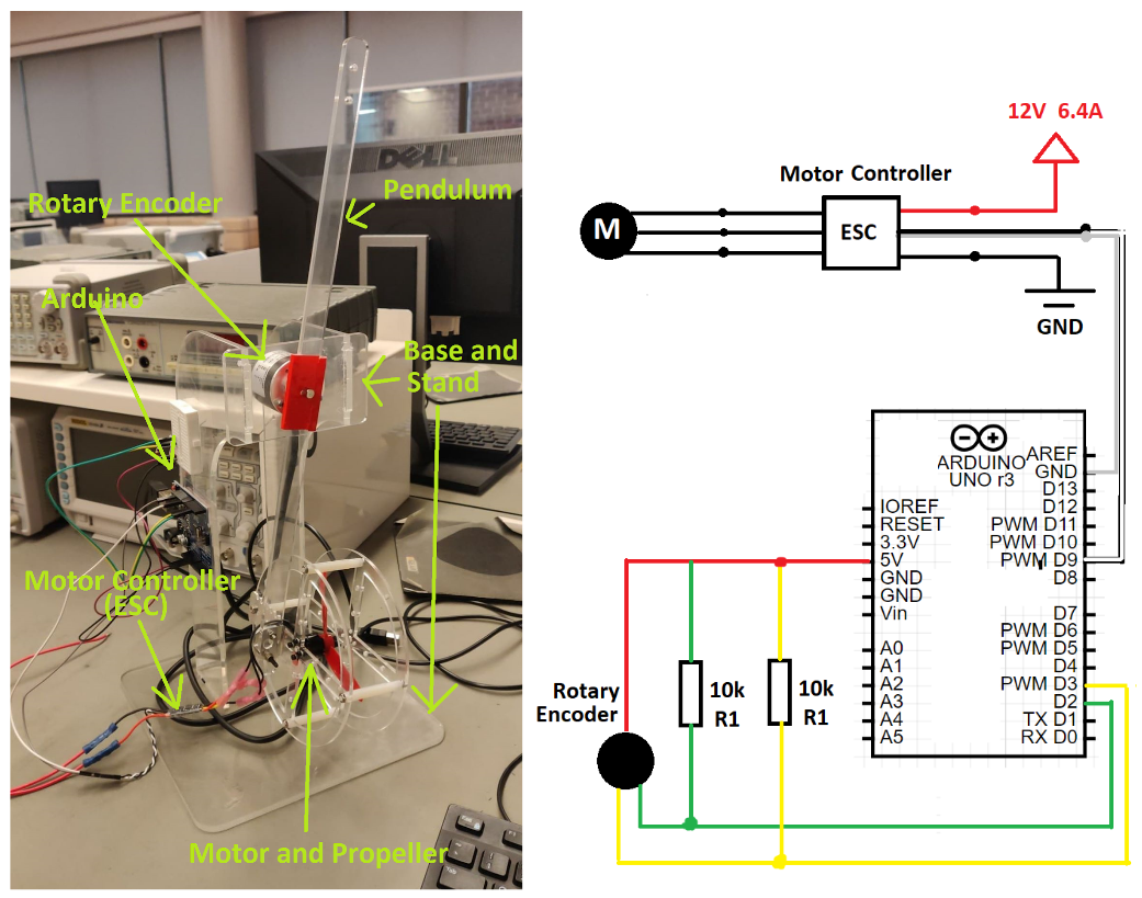
The pendulum’s angle is measured by the rotary encoder as the pendulum rotates about the shaft. The motor is connected to a motor controller (ESC) and through it the motor is powered with 12V and 6.4A. The Arduino receives a signal from the encoder, determines a new motor speed based on a PID control logic, and sends a signal to the ESC to control the motor.
Results
Step Response
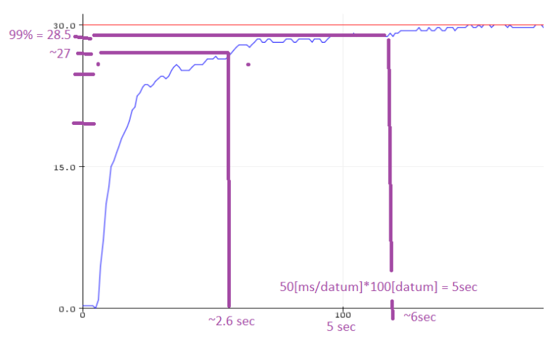
PID constants were Kp = 0.05, Ki = 0.00125 (ms^-1), Kd = 1250 (ms)
As seen in the above response, the system achieves a rise time less than 2.6 sec which meets the requirement of a 3.95s rise time. The system overshoot is negligible and therefore meets the requirements for maximum overshoot and rise time.
Displacement Correction
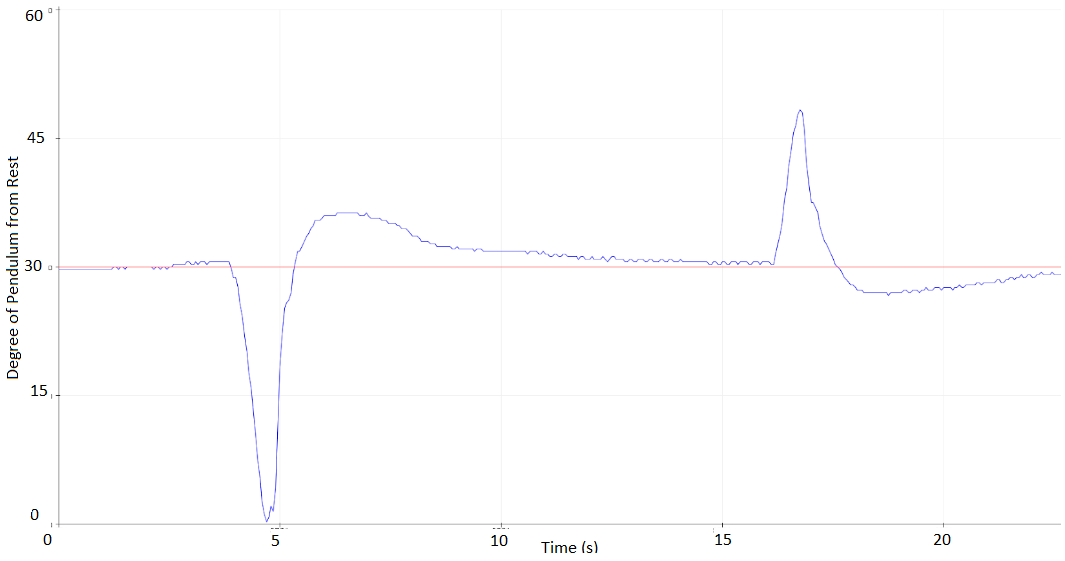
PID constants were kept the same: Kp = 0.05, Ki = 0.00125 (ms^-1), Kd = 1250 (ms)
The system responds very fast to disturbances and clearly meets the required rise time. The system overshoots by approximately 4-5 degrees for large disturbances which exceeds the system requirements of 5% or 1.5 degrees. There were hardware limitations to achieving 5% overshoot and the system at one point would meet this requirement.
Sine Wave
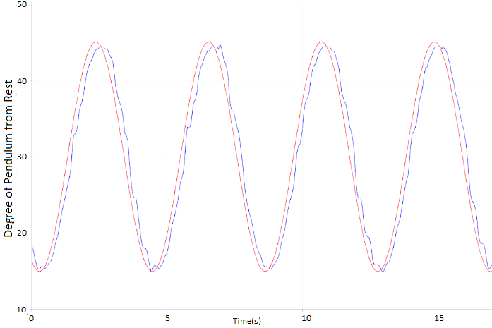
10 second period oscillating from 15 to 45 degrees. PID constants were Kp = 1.5, Ki = 0.01 (ms^-1), Kd = 200(ms)
The system responds very well to the iput sine wave. As the target is not constant steady state, overshoot, and rise time cannot be analyzed. This response was achieved mainly due to a large integral term.
NOTES:
under construction!


