To see only the CAD and FEA images, click here to go to this projects section in the CAD Portfolio
Introduction
I worked with Peter to do this. We worked on seperate ideas: Glue vs Fasteners, and both made CAD Models and did FEA. We both wrote and edited the report.
Material Properties of the Given Mateials
| Young’s Modulus | Yield Strength | Poisson’s Ratio | Density | |
|---|---|---|---|---|
| PMMA | 3.1 GPa | 70 MPa | 0.35 | 1.19 g/cm3 |
| AA110-O | 68.9 GPA | 34 MPa | 0.33 | 2.77 g/cm3 |
| Epoxy | 3780 GPA | 16.7 MPa | 0.35 | 1.16 g/cm3 |
Creating the Design
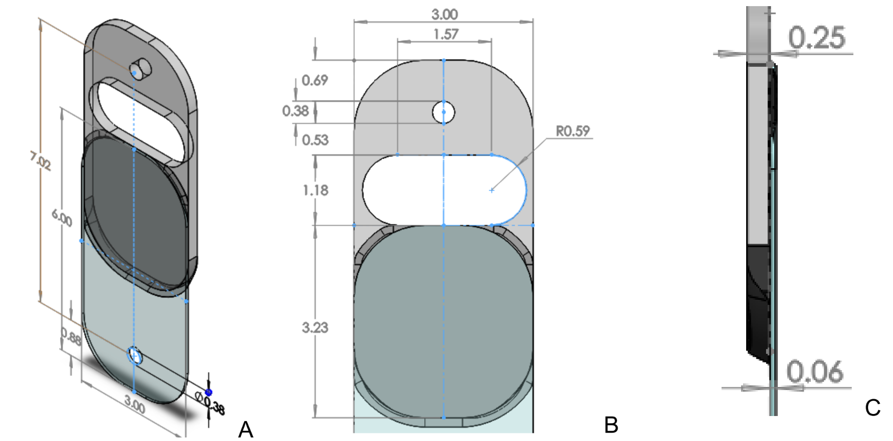
3D Model with Dimension:
ANSYS Set Up and Results:
| ANSYS Mesh | ANSYS Forces | ANSYS Results |
|---|---|---|
 |
 |
 |
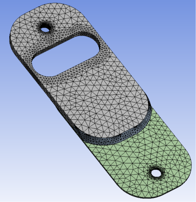
| Mesh of the joint. The mesh was refined around the holes seen here, and at the epoxy layer hidden from view. |
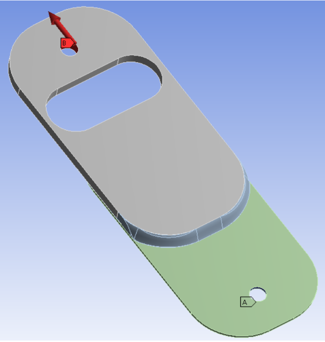
A force type load was applied at the PMMA loading hole, seen as a red vector. A fixed support was applied at the other loading hole, indicated as ‘A’. |
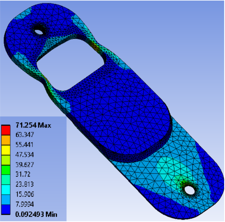
Maximum stress at the loading holes. Other points of interest were the thin arms about the hole, which had a larger deflection. |
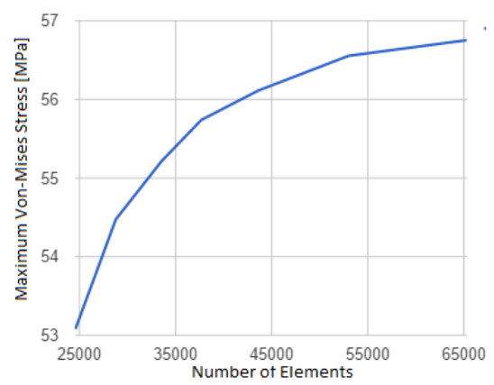
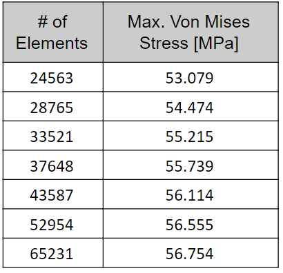
Convergence of Stress
| Graph | Table with Numbers |
|---|---|
 |
 |
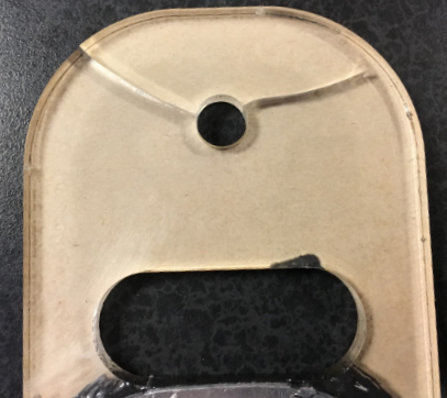
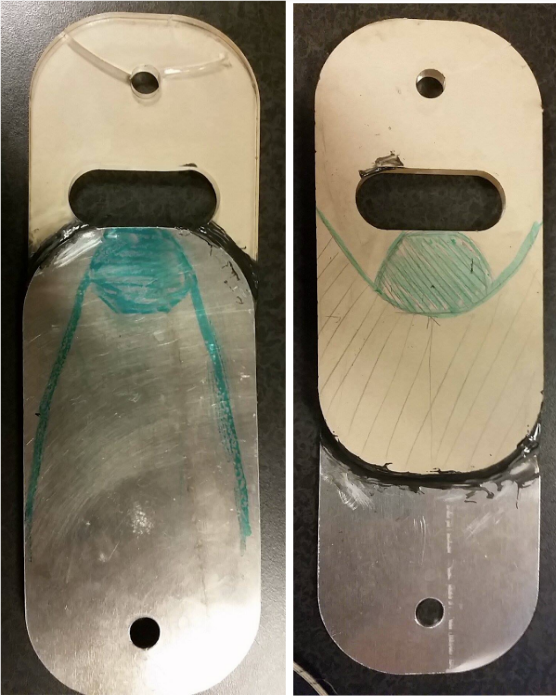
Physical Test Results and Future Work
We decided, due the brittle nature of the acrlic and due to the fact we were designing to ultimate failure, we should have used a flexible bonding material. For example, a foam tape. We also should have reduced the area on the acrylic that would have attached to the aluminum plate.
| Fracture | Potential Changes to Shape |
|---|---|
 |
 |
Notes:
Mainly just images - more work to come.
