Introduction
This was for the UofT course course MIE301: Kinematics and Dynamic of Machines. I worked in a team of 5 with Dahlia Milevsky, Julia Filiplic, Romaissa Allalou and Yiran Lu.
The project Goal was to, essentially, redesign a mechanism to have more complex kinematics. It should take a product and ideally improve it. As a result, we had near complete freedom on what to do and remake - and thus, part of the project involved creating a client, their request and how we would address it professionally (i.e. reports).
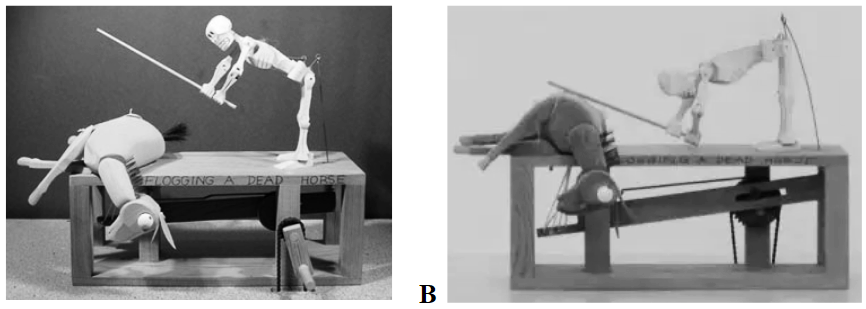
Our team decided to combine the nutcracker and an automaton toy, and make the movement to be more humanlike.
Analysis of Original Design
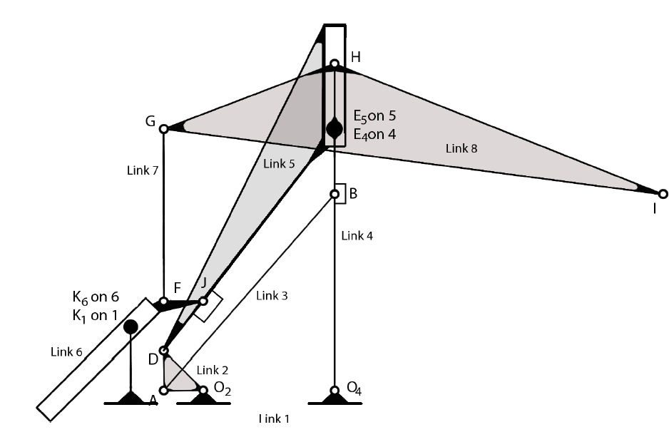
| Kinematic Diagram | With Loops for Analysis |
|---|---|
 |
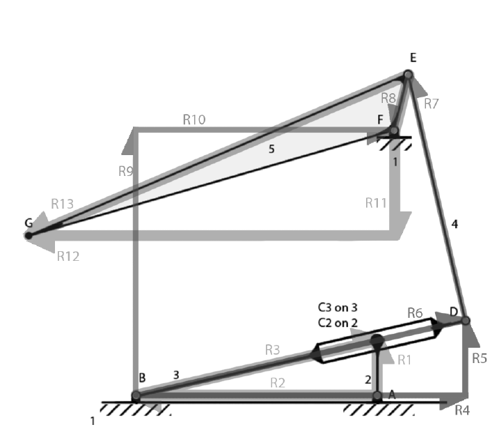 |
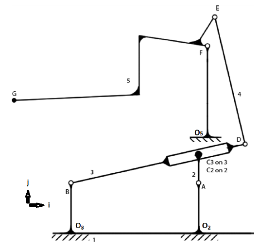
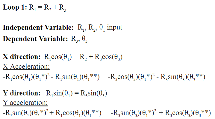
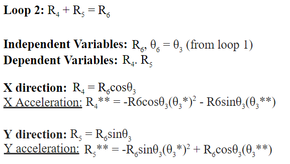
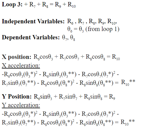
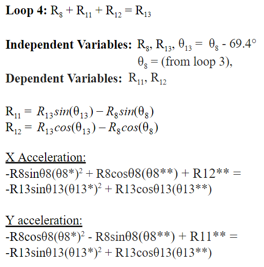
Loop analysis allows the output position, velocity and acceleration to be calculated and traced. The velocity of point G, and several acceleration formulas are needed to calculate the original force output of the mechanism for point G.
The maximum values of R11 and R12 is the position where the flogger hits the dead horse.
Loop Analysis
Click to see Loop Analysis Details!
| rAC2 = 2.8cm rBD = 17.6cm rFG = 18.6cm |
rO3_B = 4.8cm rAB = 12.4cm rDE = 13.2cm |
rEG = 21.8cm rO5_FB = 8.89cm rBC3= 12.7cm |
rEF = 3.0cm rO2_A = 4.8cm rO2_O5 = 9.4cm ĵ +0.5cm î |
 |
 |
|---|---|
 |
 |
Creation and Design of the New Design
| Simplified Kinematic Diagram of the New Design |
Kinematic Model from Simulation |
|---|---|
 |
 |
Acceleration and Force Calculations
| Graph showing composite accelerations and magnitude | |
|---|---|
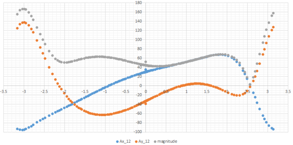 |
Blue shows the greatest acceleration along the x-axis, orange the y-axis. Grey shows the magnitude of the acceleration. |
| Graph showing only the magnitude | |
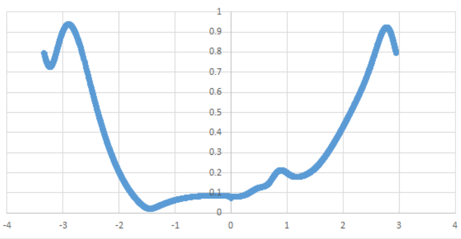 |
The greatest is 0.938m/s^2 at -3rad, or at about 3.14secs into movement with an input of 10rpm. |
| Kinematic model at point of greatest acceleration | |
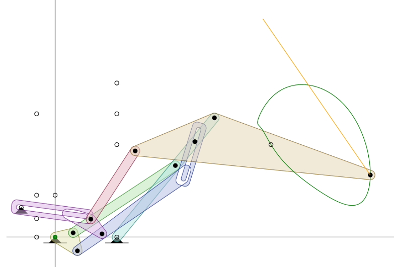 |
This is at -3rad or 3.14 secs. The Yellow line shows the magnitide and points the eopposite direction of the acceleration. |
Thus, with the acceleration known, all we need is mass to gain the force required. With research we found walnuts would reliable crack at 400Pa. We assumed the surface of the hammer is 1cm^2.
| P = F/m^2 => F = P x m^2 = 400 x 0.01 x 0.01 = 0.04N |
F = ma => m = F/a = 0.04/0.938 = 0.0426kg or 42.6g |
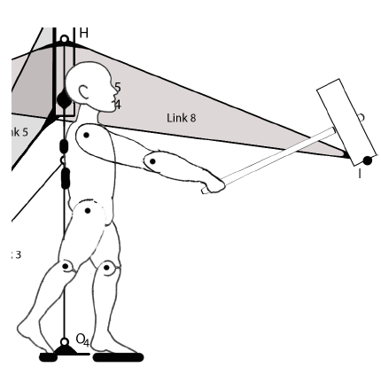
| Showing how human toy would be placed and attached to linkages |
|---|
 |
Note: you need silverlight. Currently also seems to not work for me, even with silverlight. Will need to see if anything can be done for that…
Notes
A fair amount of the writing was summarized and all the diagrams were pulled from our reports, credit to my teammates.
This page to be incomplete, but sufficient. More details and edits to be added in time.
